
.png.b54251de094ebf561cf26d6af243697a.png)
AlanM
-
Posts
7,177 -
Joined
-
Last visited
Content Type
Profiles
Forums
Gallery
Events
Store
Everything posted by AlanM
-
Switch off means the lights are not on, meaning the switch is open. Pin 1 to 4 is a bit weirder. When you turn off the switch on the pot (open it), it flips from 11.83V which corresponds to min brightness to around -6V and bounces around there a bit between -6.2 down to -6.8. Also, when checking it with the voltmeter the fan starts moving slowly.
-
Tom knows the things. I'm just doing trial and error here and trying not to fry my VDM, heh.
-
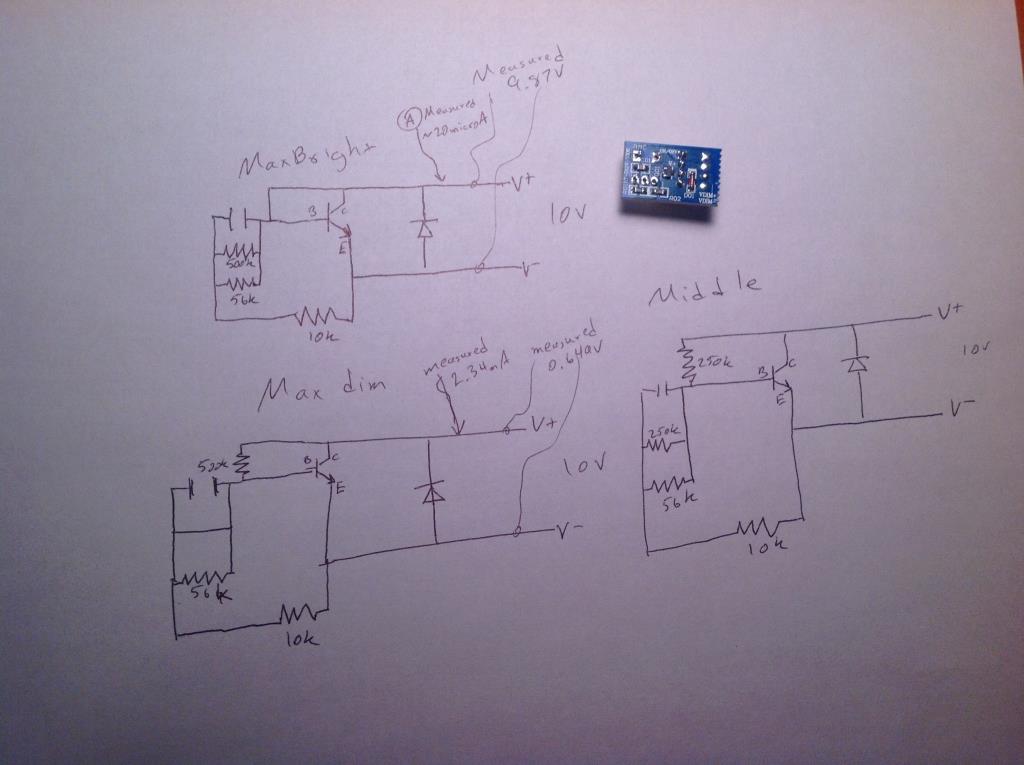
Yes, I get like 20 microAmps at full on and 2.33 milliAmps at fully dim. OK. So between pin 2 and 4 on the header I get 9.1V when the switch is off. It's nice and stable. At minimum brightness with the switch on I get 11.83V across 2 and 4 and 0.652V across 3 and 4. At maximum brightness with the switch on I get 11.98V across 2 and 4 and 9.85V across 3 and 4.
-
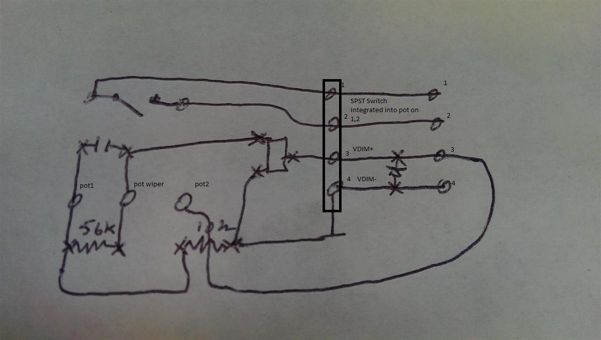
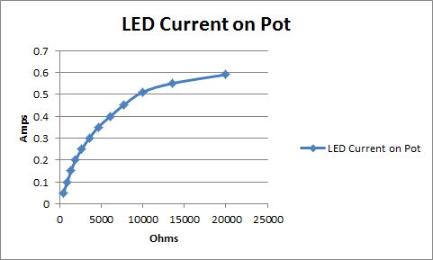
Here. I tried to annotate my sketch a bit better. I drew in the header and labelled the pins. Pins 1-2 go to the two sides of the switch built into the pot and don't connect to the dimming circuit at all. The driver supplies 10V on pins 3-4 and I can dim the lights by putting a 20k pot across pins 3-4 to drop that 10V. Max current across there is around 2.3mA at low resistance. I posted the curve of what that looks like up higher in the thread.
-
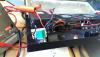
Quick update. Got lots of carpentry and plumbing done. Lights all work. Apex stuff is hung and working. Sump is drilled and plumbed to Reeflo Blowhole 1450. The tank is on the main floor, then drains go through the floor and drop 8 inches as they travel about 8 feet across the basement ceiling to the utility part of the basement where they drop where you see them in the picture below. I put a layer of Fiberglass Reinforced Panels on the walls of my fish area and caulked them in. Should help keep the water off the walls. There is a drain in the floor to the left of where the Apex stuff is hung. I have the three BeanAnimal drains in there with a gate valve on one and the return way in the corner. All 1.5" PVC. I don't have baffles in my sump yet, so I'm waiting to cut the drains to length until I do. I have a pile of Avast equipment to hook up and get running too. One of the network connections you can see is really network. The other is patched up to the tank to transmit control signals from the Apex to the Tunze 6095 powerheads. I found a great set of shelves at Lowes really cheap that happens to be exactly 36x18 in footprint and each shelf supports 1000 pounds. I'm using that for my sump area. It can be extended to 6 feet high, so I'll have room above the sump for doser containers or reactors or a fuge or frag tank or something. At the moment I'm going to put chemicals and equipment up there. Also, big thanks to Coral Hind as well. He gave me a 4x4 piece of black acrylic a couple of months back which Roscoe's Reefs was kind enough to pick up for me. I made an internal overflow box which is 36" wide and an external part to go behind the tank which covers up the plumbing and lets me bring the returns out above the water line. I think it will look really nice. I'm going to use the rest of the piece to make baffles for my sump where I may try the weatherstripping pressure method posted about recently. Getting close to getting it wet!
-
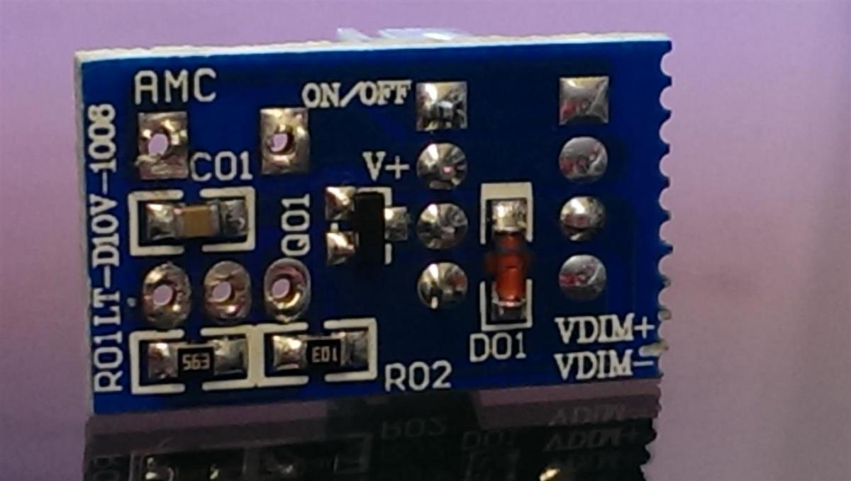
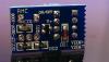
VDIM+ and VDIM- are the two bottom pins of the 4 pin header. The header is repeated twice on the board. the one on the left actually has the header on it. Here's what the top of the board looks like:

-
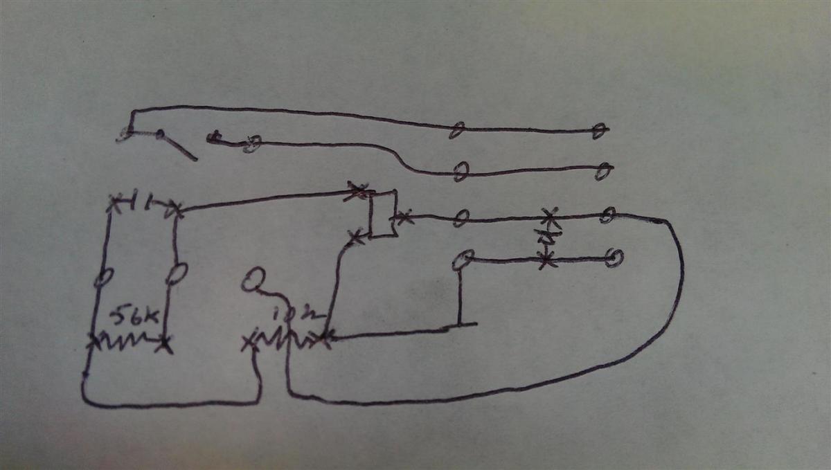
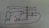
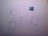
No part numbers on any of the parts including the pot except for the surface mount resistors. The transistor just says HF on it. I may have drawn it wrong. Here is a sketch of where the board traces are going after looking at it under a microscope. The one coming from the third pin on the pot goes underneath the 10k Ohm surface mount resistor, it doesn't connect to it.
-
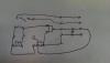
And one more showing the board that I unsoldered the pot from. I blew the transistor on this one with a battery. Doh. The top two holes are the switch, the bottom three are the two sides and wiper of the pot. the four pins on the right are top two power switch, bottom two dim+ and dim-.
-
Also, here are the other two pics attached instead of linked from photobucket.
-
Here's a little sketch I made when I was trying to figure out what the 500k pot was doing at high, low, and middle after tracing the circuit out. I didn't draw the pot right, but you can figure it out by looking where the 500k and 250k resistors are. Does this help?
-
Yeah, I read somewhere that LED drivers commonly regulate output current by watching the current across some resistor to ground and when you put a little bit of voltage on the dim wires it changes the current measurement on the calibration resistor and fools the driver into giving the LEDs less current.
-
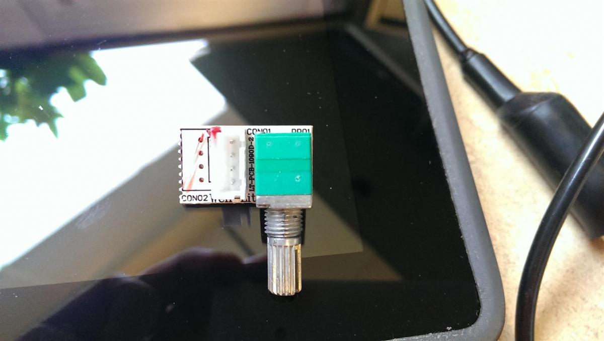
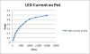
Yes, it's one of the leads on the board that the pot is mounted on. The stock pot is a 500k Ohm pot with a little board on it with a transistor and a few tapering resistors on it to make the dimming more linear as you turn the pot. The board has a 4-pin connector with 4 wires going to it from inside the driver. Picture below: Two of the wires are the on-off switch activated by the internal SPST switch on the pot. Those two wires are still connected in the picture above. The other two wires get a 10V signal sent from the driver. The driver then measures the voltage drop across those two wires. When it's 10V (meaning the resistance is high and no current flows across the dimmer wires) the LEDs are on with full current of 590mA. When it is 0V (meaning the wires are shorted and about 2.3mA flows across the dimmer wires) the LEDs are nearly off. The stock board has the low resistance at around 400 Ohms, so it never really gets down to maximum dim because they start to flicker in a very visible way. It happens at about 1V when I'm supplying a voltage rather than a resistance. Here's a plot of pot resistance vs LED current: Lately, instead of using a pot, I supplied a voltage and was able to see that the dimming works really well when just putting an opposing 10V across the dimmer wires, essentially dropping the voltage across an opposing voltage rather than across a resistor. It worked really well. The problem with this approach is that current still wants to flow, and the device supplying the opposing voltage might not like current going in to it's positive terminal and out it's negative terminal. The Apex folks, RussM in particular, said that under no circumstances should current flow back in to the VDM ports. I'm wondering if a diode would fix the issue and still let the voltage get through. I don't really know about op amps or how I'd use one to buffer the voltage. Do you have a pointer to read?
-
Thanks for the warning. I will try to be careful. Hmm. Maybe I should borrow someone else's VDM to try it with, heh.
-
So I know now I can control it from 0-100% with just a 20k digital pot, but after playing with it some more today with a bench-top CC/CV power supply it seems like it could be as stupidly easy as just putting the Apex 0-10V outputs across the dimming pins. It dimmed nicely from 0 to 100% just by supplying 0-10V. It never drew more than 2.5mA of current in either direction from the bench supply, so I don't think it will hurt the Apex modules, but I posted a question about it on the Neptune forums just to be sure. If I don't hear anything back in a day or two I'll just give it a try and try not to blow anything.
-
I missed this somehow. The aquaticlog site looks really nice. Will sign up there and pay once I've got the tank running.
-
I was trying to remember the name of that thing. It looked nice. I think one was a raffle prize two meetings ago.
-
I really like the lots of caves and arches and columns. Seems like this would give you the opportunity to get some more territorial/agressive fish since there will be plenty of places for folks to claim and plenty of places to escape to. Also, dod you stick them together with marco putty?
-
Too weird that those are BRS bulkheads too. Wonder what they sent when I ordered my sch80 ones. I ended up replacing them with ABS ones because I just couldnt get them to hold a pipe, and they are sitting downstairs now waiting for a use.
-
Isn't that the bottom of your external with the bulkheads? I thought you cracked it? Or are you taking them out the back? I thought most people who do externals take them out the bottom of the external box. One more question. What bulkheads are those? I'd got some sch80 1" ones from BRS via QR that came in with the flange side so tapered that no pipe I put in would actually seal. It just rattled around in there because of the gradual shoulder that went down into the fitting. Looks like those would have worked well for me. Edit: BTW, I just drilled the bottom of a 40B that I'm using as a sump. I'd planned the hole location all out measuring from above, then flipped the tank over on the floor and drilled with no template or anything using the tip-the-bit to get it started trick and a dam of putty. It worked fine, and I was through in like 5 minutes. It wasn't until I flipped it back up that I realized that I'd just drilled the wrong corner since I was working upside down. Doh! Should be fine though.
-
It won't really hurt you to breathe some. Pull out the tube, crank up the volume, put it under your nose and see what it smells like. 8) It's kind of a sharp smell. EPA says it takes long term exposure to get ya. Chronic, not acute. http://www.epa.gov/iaq/pubs/ozonegen.html
-
Maybe use canola oil instead of water for lubricant? More viscous and maybe less messy? Ooh, or fish oil, then you dont even have to worry about cleaning it, heh.
-
Ooh, you drilled it? How many holes between inner and outer?
-
mA V Ohm LED Current LED Voltage 0.2 9.81 481000 0.59 82.7 0.35 9.77 0.38 9.76 467000 0.57 8.99 0.57 0.59 8.87 460000 0.56 0.76 8.04 0.51 0.77 8.01 446000 1.03 6.79 0.42 1.11 6.44 397000 0.39 1.3 5.52 0.33 1.41 5.03 301600 0.3 1.52 4.51 1.63 3.96 0.23 1.67 3.79 241900 1.75 3.419 1.84 3.002 194300 0.18 1.86 2.868 0.16 1.96 2.43 2.02 2.15 143000 0.12 2.13 1.631 0.09 2.16 1.47 104200 2.18 1.366 0.07 2.26 1.016 0.05 2.33 0.672 60000 0.04 65.4 Here's a table of data collected on the little dimmer board and on the wires going to the string of LEDs on one channel. The LED current goes from 40mA at all the way dim up to 600mA at full brightness. The voltage dropped across the 28 (or maybe 27) LEDs goes from 65.4 up to 82.7. The other measurements were taken across the pot board. The Ohm column isn't what the circuit actually sees. It's an offline reading on the output of the board where I disconnected it at those settings and did a separate measurement.
-
I can't tell if that's a brass spigot or if it's 38 year old yellowed phenolic resin. Maybe he has a Bakelite valve to drain his skimmer body. 8)
-
What is the power consumption of a UV based ozone generator like the Ultralife mini? I can't find it listed anywhere. And is it really just that easy to hook up? Plug it in and put it inline in the skimmer intake? (With the caveat that the ozone might wreck the plastic along it's path).
.thumb.png.40db71e145957fbc22a7d873e5f3065b.png)