HDReef January 3, 2011 January 3, 2011 This thread is the build thread for my wife and my 75g reef tank. First here is a little introduction to who we are. My name is Darrell; my wife Holly and I are new here at WAMAS. I have lots of experience with fresh water tanks from when I was younger but I always wanted a saltwater tank, so I spent the last couple years researching saltwater tanks and finally took the leap into the hobby. It is a 75g reef-ready display tank and a 75g basement sump. When the system is done it will also include a 40g frag tank in the basement, plumbed to the rest of the system. To start, we found 2 used 75g saltwater systems on Craigslist and bought those as a base to our system. This will be our 75g display tank. It came pre-drilled/reef-ready. This is also the location we chose for the display tank in our house. Before placing the tank here we leak-tested it outside. This is the equipment we received with the above tank. These 2 T5 2-bulb light fixtures also came with this tank. These will probably be used over the frag tank. This is the second 75g tank we received. We are only using the tank and it is for our sump in the basement. We are planning to sell the unused stand and canopy to help offset the costs of start up. This is the equipment we received with the second 75g tank. Additional posts to follow with our progress.
HDReef January 3, 2011 Author January 3, 2011 We leak-tested the 75g tank for the sump outside when we first received it. And although we found no leaks, the inside seals looked really rough. So step one was to reseal the 75g tank for the sump. We started by getting our tools ready. (Rubbing alcohol added later) The first thing we did was to take off the rim of the tank. This is not as easy as everyone makes it out to be. This by far was the longest and hardest process of the tank being transformed into the sump. If you ever have to do this, might I suggest rubbing alcohol to loosen the silicon. After struggling with it for well over 3 hours with little progress, we decided to try the rubbing alcohol. With the tank upside down, we poured it (not a lot) into the rim and let it sit for 15 minutes max. We were then able to pry it off the tank. Here we are working the rim off, making sure not to break it so we could install it later. Here is the rim finally off the tank! We then removed the silicon seals inside the tank with razor blades, being careful not to stick the razor blade in between the seals of the glass. We then taped off the edges where we wanted to keep the silicon. We made the silicon seals a little large in the sump to ensure the tank is strong for when we are adding and removing equipment in the sump. Since this is not the display tank, we felt the larger seals were fine. This is one of the completed seals. After completing the seals, we reattached the top trim and let it sit to set. (Sometimes you have to improvise - in this case cases of soda make good weights. lol)
Origami January 3, 2011 January 3, 2011 Nice job! Thanks for posting. I'll enjoy following your thread. And, by the way, welcome to WAMAS!
Happyfeet January 3, 2011 January 3, 2011 Welcome to WAMAS! Good to know about the rubbing alcohol, I got fed up and just got a new tank ha!
HDReef January 3, 2011 Author January 3, 2011 While we were resealing the tank, we ordered some other equipment we would need. Here is our light fixture. It is a 6-bulb T5 and moon LED light fixture from IceCap. We also order 120lb of base rock from BRS. It is 100lb of Reef Saver Rock and 20lb of Pukani Rock. This will be split between the display tank and the refugium in the sump. We then got a Blueline HD55 return pump from our lfs. This is the light fixture on the tank.
HDReef January 3, 2011 Author January 3, 2011 So the next thing we decided to work on was getting the display tank ready. We decided to paint the background on the display tank rather than using a stick-on background to prevent salt creep in between the background and the glass. Here we have taped off the tank. We chose blue from Home Depot and here it is painted. Due to the setup of our house and the placement of the tank, the corner overflow would have been very visible. So we had my work custom make a small stainless steel corner piece to cover it. I spray painted it black to be discrete. We also added sticky velcro to easily remove it when we need to see in the overflow. This is the corner piece mounted on the tank. Since we are not using a canopy and we plan to get a firefish (which are known jumpers) we made fitted clear-net screen covers for the top of the tank. We used screen window framing. These are the frames just before we added the clear quarter inch screen we got from BRS. This is the tank with the background painted, the corner cover piece attached and the light fixture on.
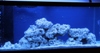
HDReef January 3, 2011 Author January 3, 2011 Now came the rock work in the display tank. We purchased thin, clear knitting screen from a craft store and attached it to the bottom of the tank with silicon. This was to have a base for the rocks to sit on to prevent having a stress point from the rocks against the glass. And we needed to purchase one more piece of equipment...The pictures should look better from here on out. Now we were ready for the rocks. We laid out the rock structure before we set them in the tank to make designing easier. This was our final draft after trying many configurations. We then placed the rock in the display tank and added our sand. We rinsed the sand before putting it in the tank. The rock was placed in first so that no sand-sifters could dig underneath the rock and unbalance the structure. After that we placed painter's plastic over the rock structure and sand to prevent displacement of the sand when adding water to the tank. Time to level the tank. This was the last thing we worked on in our display tank until after we began the sump.
HDReef January 3, 2011 Author January 3, 2011 The first step we took on the sump was leak-testing it after the resealing was dry. Luckily there were no leaks so we were able to begin the remaining work on the sump. We purchased a glass hole drill stabilizer and bit off eBay to add a hole to the side of the sump tank for a bulkhead for the return pump. We used plumber's putty around the area we were drilling to hold in water to keep the bit cool. This is me drilling the hole. This was the first time I ever drilled glass. It was pretty nerve-wracking because we spent so much time on the resealing (due to the top trim - see above ) and were afraid of cracking the tank. Hole was a success! There was also some de-struction that had to take place to make room for the sump downstairs. Here are the plans for the stand for the sump tank. And so we began...here is the base to the stand. The leg and the upper frame are now complete. Almost done - all that remains are the top braces. This is the tank on its stand, downstairs in its final position. You may notice the baffles have been added to the sump as well; we did not take pictures of those being installed. At this point, with the display tank and sump ready for water, it was time to complete the piping.
HDReef January 3, 2011 Author January 3, 2011 Nice job! Thanks for posting. I'll enjoy following your thread. And, by the way, welcome to WAMAS! Welcome to WAMAS! Good to know about the rubbing alcohol, I got fed up and just got a new tank ha! Thanks for the welcomes! Regarding the rubbing alcohol: we were almost to the point of buying a new tank too. The rubbing alcohol really seemed to help loosen the silicon a lot.
HDReef January 3, 2011 Author January 3, 2011 At this point with the sump and tank ready, it was time to do the piping. First, I began to piece together the smaller portions of the piping. I put together the smaller pieces of PVC and their elbows. Once I had them ready, I plumbed them through the floor first to lay out the position of the pipework. This is the piping under the display tank. The short barbed piece of pipe is the drain and the return is the longer PVC piping. We added a gate valve to the return to be able to adjust the amount of flow going into the tank. After this piping was done, we added flexible tubing and pipe clamps to the barbs to complete the upstairs piping. Next, we plumbed the pump. We included unions and ball valves to be able to shut off the water and remove the pump in case of cleaning or maintenance. There is also a strainer on the pump intake to prevent anything from entering the pump. We then worked on the larger pieces of pipe that connected the display tank to the sump. This is along our basement ceiling.
HDReef January 3, 2011 Author January 3, 2011 After the piping was complete it was time to fill the tanks! This was one of our basement walls before. And this is after. We mounted a 5 stage RO/DI unit with booster pump to the wall for making water. After the water was made, we began adding it to the display tank. When the tank was halfway full, as shown in the picture, we re-leveled the tank. Next we added the remaining base rock to the refugium in the sump and filled the tank. Next came the leak tests. This is the sump running. Luckily there were no leaks!! This is our display tank with water running and the lights on. And here we are finally! As of this posting this is our progress thus far. The tank has been running with water for four days just to be extra sure there are no leaks. At this point, we are ready to add the salt, heaters, protein skimmer, and powerheads. So our next step is finding a few quality pieces of live rock to start seeding the tank. We are also going to add some cheto to the refugium. If you have any, please see my topic in the For Sale/WTB section Here. Stay tuned for more updates and pictures as the tank progresses.
WaterDog January 3, 2011 January 3, 2011 Looking good so far, and welcome to WAMAS. It's great to see everything coming together.
FearTheTerps January 3, 2011 January 3, 2011 (edited) Welcome To WAMAS. This has to be the best noob build thread Ive ever seen. You are off to a great start, seems like you did do alot of research beforehand, and it shows that all that research paid off. Great Job!!! Quick question, is the stand for your pump attached to the sump's stand? I ask because I would worry about the pump being bumped into or moved, especially with that doorway being there. With the hard plumbing and the weight of the pump, I dont think the glass on the sump would stand a chance and cause a horrible failure. Are you using GFI's? I see one by the sink, but the return pump doesnt have one. Looking forward to seeing more progress, now the cycle awaits. Edited January 3, 2011 by FearTheTerps
HDReef January 3, 2011 Author January 3, 2011 Welcome To WAMAS. This has to be the best noob build thread Ive ever seen. You are off to a great start, seems like you did do alot of research beforehand, and it shows that all that research paid off. Great Job!!! Quick question, is the stand for your pump attached to the sump's stand? I ask because I would worry about the pump being bumped into or moved, especially with that doorway being there. With the hard plumbing and the weight of the pump, I dont think the glass on the sump would stand a chance and cause a horrible failure. Are you using GFI's? I see one by the sink, but the return pump doesnt have one. Looking forward to seeing more progress, now the cycle awaits. Thanks so much for the compliments! To answer your questions: Currently the pump stand is not attached to the sump stand. The stand that the pump is sitting on now is temporary. I will be building a new pump stand in the near future. I was not planning on attaching it to the sump stand, but now that you bring that up, I will. Thanks. For the GFIs, everything will be going into GFI outlets. I am about to add another fuse to our fuse box. This fuse will be for the aquarium only and will go to a bank of outlets by the sump, all will be GFI. The pump being plugged in there is just temporary. Everything on the display tank will also be plugged into GFI outlets. Good catch on the outlets. Darrell
iangibby January 4, 2011 January 4, 2011 Welcome and very nice build!! Just my 2cents, try to avoid plugging your lights in the gfci circuit. The ballasts will cause the gfci to trip I learned that the hard way.
HDReef January 4, 2011 Author January 4, 2011 Welcome and very nice build!! Just my 2cents, try to avoid plugging your lights in the gfci circuit. The ballasts will cause the gfci to trip I learned that the hard way. I have heard this before and was told that it depended on the ballasts in your light fixture. So I will keep an eye on this and if there is a problem I will switch the lights to non GFI outlets. Thanks. Darrell
Origami January 4, 2011 January 4, 2011 Another couple of things to consider, Darrell, are 1) what happens to the water level in the sump when the power goes out, and 2) what happens to the water level in the display should the drain to the sump get blocked. Both failure modes could lead to water on the floor. In the first case, it would be water on the basement floor both from water siphoning down the return pipe back into the sump; and, in the second, water on the floor of the main level as the water in the last sump chamber is emptied into the display. To avoid the first, you typically drill a hole into the return plumbing inside the tank, just below the water line, which acts as a siphon break, to stop the siphoning action. In the second case, you just ensure that your display has sufficient unused capacity to handle the water in the last chamber. I don't see any obvious oversights in this regard, but I thought I'd mention it just to make sure the bases are covered.
HDReef January 5, 2011 Author January 5, 2011 Another couple of things to consider, Darrell, are 1) what happens to the water level in the sump when the power goes out, and 2) what happens to the water level in the display should the drain to the sump get blocked. Both failure modes could lead to water on the floor. In the first case, it would be water on the basement floor both from water siphoning down the return pipe back into the sump; and, in the second, water on the floor of the main level as the water in the last sump chamber is emptied into the display. To avoid the first, you typically drill a hole into the return plumbing inside the tank, just below the water line, which acts as a siphon break, to stop the siphoning action. In the second case, you just ensure that your display has sufficient unused capacity to handle the water in the last chamber. I don't see any obvious oversights in this regard, but I thought I'd mention it just to make sure the bases are covered. For the first 'failure scenario,' the water level in the sump will not overflow. We have tested this already by shutting off the pump and letting the water drain down. The display tank, with the pump off, drains down to the water levels shown below: Here is our return lines in the display tank. The water stops siphoning into the sump once the water drains below them, as shown here. Please note the water movement you may see is from the powerheads, not the return lines. With this picture the water in the overflow only drains until the hole is met. So with the water at these levels in the display tank, the sump will still have 3 inches of room before it would overflow. As for the drain getting clogged, we have thought about that and it would most definitely cause an overflow. However, we came up with no perfect solution to prevent this. Our only thing we plan to do is make a form fitted covering for over the top of the overflow in the display tank to try and prevent a clog. (i.e. snails, large debris, etc.) Thanks for the comments; keep 'em coming! If you do have any suggestions for the second scenario, please let us know! Holly
HDReef March 21, 2011 Author March 21, 2011 Finally finished our cycle and got our cleanup crew!!! Hopefully we will get a chance to update this sometime this week. Lots of stuff to update Holly & Darrell
amay121 March 21, 2011 March 21, 2011 Looks great. Good luck with the setup. Can't wait until you get more livestock in there.
HDReef March 26, 2011 Author March 26, 2011 After a long hiatus, we are able to update you all on our 75g tank. Much has gone on since January and we are excited to have pictures for you now. We had added salt and once the salinity was where we wanted, we were ready to add our first pieces of live rock. We first added two powerheads in the DT. We then added heaters to bring the water up to temp before adding the live rock. We also added Tyvek to our basement ceiling above the sump as our basement is not finished at this time and this would prevent things (fiberglass, dust, etc) falling in the tank. We then added live rock. The first picture is a piece of live rock in our display, and the second picture is a few smaller pieces in our sump, as well as some cheto. We added this on 1-8-11. Thanks to gwweber for the live rock and cheto to get the tank started! To start our cycle, we added a couple of large pinches of flake food to the tank. We added the skimmer and the refugium light at the same time we added the live rock. We plugged all of this new equipment into our homemade portable GFCI outlets. You can find our DIY thread here.
HDReef March 26, 2011 Author March 26, 2011 While we were waiting for the tank to cycle, we decided to work on making light hanger posts for our T5 lights. The reason we wanted to do this was that it was getting to be a pain to have to remove the light to do anything inside the DT... First we cut some metal conduit pipe to the length we thought would work best for our hangers. We then attached 90 degree bends with couplings. Here are the two completed uprights. We then began working on the base. We took a 2x4 and attached metal conduit clips to ensure the poles stayed in place. We then spray painted everything black to match the light. Once dried, we added the hangers to the tank, securing them in place in the back with c-clamps. These pictures show the finished hangers. We also decided to purchase an APEX controller to further improve our automation of the tank and allow us to receive notifications in the event that something goes wrong while we are not home. Please ignore the numbers as this was taken before the pH or temp probes were added.
HDReef March 26, 2011 Author March 26, 2011 Also during our wait, we had some algae... These photos show the algae that we collected while the tank was cycling. We also had a problem with the heaters not being large enough for the tank so we got some new ones. During this time, we continuously checked the tank for ammonia, nitrite, and nitrate. The nitrite dropped to 0 after about 1 month, but the ammonia stayed for quite a bit longer...FINALLY, after a few months of testing the tank, on 3-15-11 we got a test back that showed 0 ammonia. A week later, we got our clean up crew: 12 dwarf blue legged hermit crabs, 12 nassarius snails, and 25 cerith snails. We are now ready for fish and corals and plan to keep updating the build thread with our new aquatic pets. Thanks for all your comments! Holly and Darrell
Chad March 26, 2011 March 26, 2011 Looking good, I like your very clean DIY work. It is all about the details.


Recommended Posts
Create an account or sign in to comment
You need to be a member in order to leave a comment
Create an account
Sign up for a new account in our community. It's easy!
Register a new accountSign in
Already have an account? Sign in here.
Sign In Now