.jpg.cec6c540fb2da6431942d5ff09ef7a2d.jpg)

.png.b54251de094ebf561cf26d6af243697a.png)
AlanM
-
Posts
7,152 -
Joined
-
Last visited
Content Type
Profiles
Forums
Gallery
Events
Store
Everything posted by AlanM
-
Ok, so the opamp should still get power from the header pins 2 and 4, and that's what I'm testing right?
-
I do have an old Fluke Scopemeter that I can check between pins 3 and 4 to see what is coming out. I'm nervous about shorting pins 3 and 4 since the Apex input is on those. Dave S said the following earlier in this thread:
-
I ordered the weatherstripping from McMaster-Carr that they cite in the article and just installed some baffles. No water in it yet. Will do that tonight or tomorrow night and let folks know how it holds and if it leaks.
-
Yeah, if you open the box you can see if it's brown wire and black wire.
-
Haha, nope. I'm a dummy. I just don't mind clipping wires that I'm pretty sure I can get back together. Remember I already let the smoke out of one of my dimmer boards on the d120 with a battery, so now I have to get it working. 8)
-
It's not old telephone cord. It's cat5, and I say what they are in my post, blue/white is 0-10v from Apex, green is negative from Apex (ground). I also describe what those black and red ones are in my post. I also describe how I pulled the two resistors with no change. 0.25Amps is on the LED light string, not on the Apex or the dimmer lines. 250mA is the lowest current it goes to with the opamp between the Apex and the d120. When hooked up directly up to the Apex it goes to 170mA on the LEDs. I don't know if pin6 follows pin3. I'll check. What do I reference them both to to check? Pin 4?
-
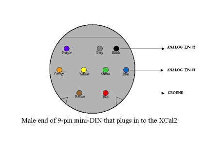
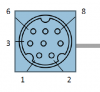
It should definitely be switch 1. It's normally closed when the water level is low and opens when the water level rises in the sensor tube (or if you blow on it). Continuing my sacrificing my stuff in the name of science, I clipped the mini-din9 connector off the locker I bought. I want to put it into the breakout box instead of directly into the Apex so I can put in some float switches and water sensors too. The Avast locker sensor uses the brown wire and black wire of a mini-din9 which are hooked to the connector as in the image below. The comprehensive guide to Apex numbers the pins like the image below with 1 on the bottom left and working your way up to 6 on the top left. Number 8 on the top right is the common for all of them (black wire). 7 is unused. So if you put an ohmmeter between pins 1 and 8 on your connector you should see continuity that goes away when you blow on the sensor. If it doesn't, maybe yours is broken.
-
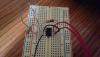
Tom, With the op-amp hooked up as you describe above the minimum current is 0.25A on the LED. It does ramp up to 0.58A similar to the direct hookup. With it hooked up directly to the Apex the minimum is 0.17A. I tried it with the 100k and 20k resistors and without them, and there was no difference either way. Here is a pic attached of how I hooked it up. The red wire you see coming from pin 7 on the 741 goes to pin 2 on the d120 header (which is shorted to pin 1 to get the lights to turn on). The red wire from pin 6 of the 741 goes to pin 3 on the d120 header and the black wire from pin 4 goes to pin 4 on the d120 header. The blue/white is 10V from apex, the green is ground from apex. Do you see something wrong?
-
I only know how to do it with the web interface, which I assume the Jr has. Just click on Outlets under configuration and pick the one you want to rename from the dropbox one at a time and start renaming them in the text box and hitting save. Then on the front dashboard that loads as the default turn them on/off as your heart desires. They're probably named things like "Skimmer, pump, powerhead" and stuff right now.
-
You could at least rename the outlets on your powerbar with what is plugged into them. Oh, and the default is that theyre set to auto with some default program that turns them on and off all the time. You should set them to off or on if you want to use them as a powerstrip.
-
I will post pictures when I get back from my in laws house tomorrow. But some of the other pics on the thread here may help. There are pics of the dimmer boards at least.
-
Especially since it is in the wall an external overflow seems perfect. Could also try one of these type. http://www.reefcentral.com/forums/showthread.php?t=2160311
-
Cut a slot in the top of the back and glue a box on the outside of the back with holes drilled on the bottom for drains. External overflow box. I guess youd plug the existing internal holes on the bottom or use em for a closed loop.
-
will do. Good idea.
-
Haha, right, but I hope this wouldn't fry your router with only 2.33mA.
-
It works!!!!1!!1!! The easiest way possible, like Tom thought it would. Video below. I just decided to risk sacrificing my VDM in the name of scientific progress. I did what Tom suggested to just try hooking the darn thing up to the VarSpd ports on the Apex and drive them. It works just fine. In the video you can see my little multimeter measuring current on the LED string. I flipped the outlet that activated a ramp profile to go to 0 to 100 in 1 minute. Max current is 580mA (I hooked it up backwards in the video), which is right. The min current is 170mA, so it doesn't dim as low as it does with the pot, probably because the Apex, has a little bit of internal resistance even when you're not supplying a voltage on the VarSpd ports. I have the d120 plugged into outlet 1 of my EB8 and called that one d120s and turned it off to turn it off all the way. So it seems all you need to do to control it is to get a little 4 pin header, unplug the pot board, short out pins 1-2 to power it on, then hook up pins 3 and 4 to the + and - wires coming out of the Apex VarSpd port. Or just snip off the connector and solder the wires together. Ooh, or cut a little square in the metal panel on the top and put a keystone RJ45 jack, then you could just use a Cat5 patch cable to go between the Apex and the d120.
-
Well, we had a drawer of 741 chips, and lots of resistors, so I will try that first and then do apex directly.
-
Will try it this evening.
-
I now get why it is called a unity gain amplifier. It isnt giving more current. It is just isolating the Apex side from the driver sense circuit side. I will risk the VDM by just hooking it up across the snipped wires which used to go to pins 3 and 4 to see what happens since I really did only see a couple milliamp through there. In that case I dont have to set it to max bright at all because the dimmer board is not even in the picture. I dont think pin 1 and 2 are supplying current to the auxiliary board at all, by the way. When I look at the traces those two pins go right in and out. Unless it goes back in to the driver and out to the dimmer board.
-
Switch off means the lights are not on, meaning the switch is open. Pin 1 to 4 is a bit weirder. When you turn off the switch on the pot (open it), it flips from 11.83V which corresponds to min brightness to around -6V and bounces around there a bit between -6.2 down to -6.8. Also, when checking it with the voltmeter the fan starts moving slowly.
-
Tom knows the things. I'm just doing trial and error here and trying not to fry my VDM, heh.
-
Yes, I get like 20 microAmps at full on and 2.33 milliAmps at fully dim. OK. So between pin 2 and 4 on the header I get 9.1V when the switch is off. It's nice and stable. At minimum brightness with the switch on I get 11.83V across 2 and 4 and 0.652V across 3 and 4. At maximum brightness with the switch on I get 11.98V across 2 and 4 and 9.85V across 3 and 4.
-
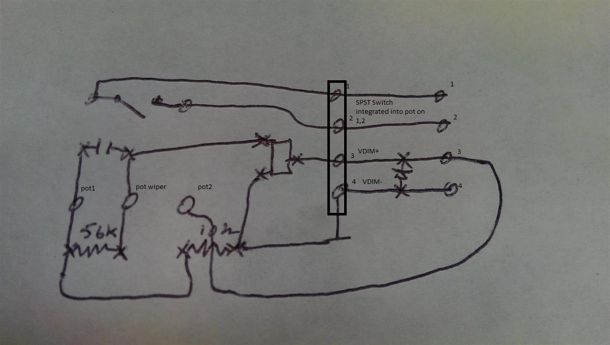
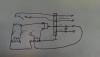
Here. I tried to annotate my sketch a bit better. I drew in the header and labelled the pins. Pins 1-2 go to the two sides of the switch built into the pot and don't connect to the dimming circuit at all. The driver supplies 10V on pins 3-4 and I can dim the lights by putting a 20k pot across pins 3-4 to drop that 10V. Max current across there is around 2.3mA at low resistance. I posted the curve of what that looks like up higher in the thread.
-
Quick update. Got lots of carpentry and plumbing done. Lights all work. Apex stuff is hung and working. Sump is drilled and plumbed to Reeflo Blowhole 1450. The tank is on the main floor, then drains go through the floor and drop 8 inches as they travel about 8 feet across the basement ceiling to the utility part of the basement where they drop where you see them in the picture below. I put a layer of Fiberglass Reinforced Panels on the walls of my fish area and caulked them in. Should help keep the water off the walls. There is a drain in the floor to the left of where the Apex stuff is hung. I have the three BeanAnimal drains in there with a gate valve on one and the return way in the corner. All 1.5" PVC. I don't have baffles in my sump yet, so I'm waiting to cut the drains to length until I do. I have a pile of Avast equipment to hook up and get running too. One of the network connections you can see is really network. The other is patched up to the tank to transmit control signals from the Apex to the Tunze 6095 powerheads. I found a great set of shelves at Lowes really cheap that happens to be exactly 36x18 in footprint and each shelf supports 1000 pounds. I'm using that for my sump area. It can be extended to 6 feet high, so I'll have room above the sump for doser containers or reactors or a fuge or frag tank or something. At the moment I'm going to put chemicals and equipment up there. Also, big thanks to Coral Hind as well. He gave me a 4x4 piece of black acrylic a couple of months back which Roscoe's Reefs was kind enough to pick up for me. I made an internal overflow box which is 36" wide and an external part to go behind the tank which covers up the plumbing and lets me bring the returns out above the water line. I think it will look really nice. I'm going to use the rest of the piece to make baffles for my sump where I may try the weatherstripping pressure method posted about recently. Getting close to getting it wet!
-
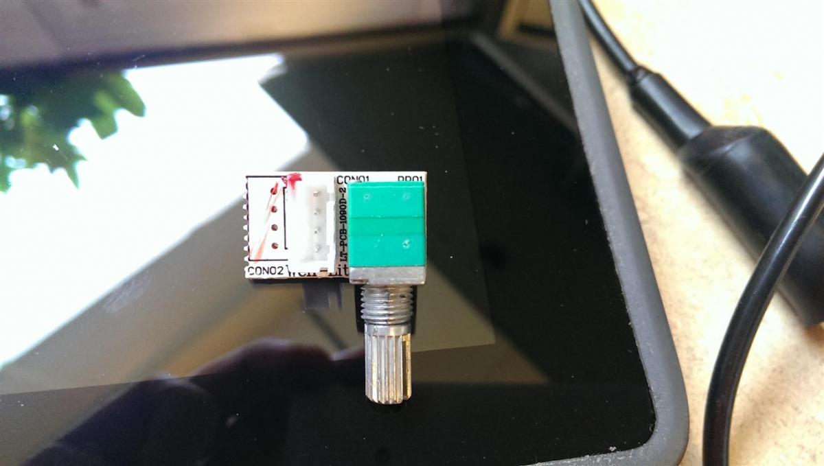
VDIM+ and VDIM- are the two bottom pins of the 4 pin header. The header is repeated twice on the board. the one on the left actually has the header on it. Here's what the top of the board looks like:

.thumb.png.40db71e145957fbc22a7d873e5f3065b.png)